Hello everyone. My name is Atmega32. I belong to the AVR family of Atmel’s microcontrollers. We are a very well-cultured and user-friendly family. I am the most commonly used controller for beginner robots along with Microchip’s PIC microcontrollers (though I don’t like it...it is cheap!). The reason why people so commonly use me is that a variety of development tools are available for working with me and for exploiting my features to the best. Over the years, my manufacturers have been increasing my flash memory, so that you can stuff me with bulkier and bulkier codes and hence, I can do more for you. Please learn to use me well. Some time ago, beginners tried to use me without properly reading the datasheets and learning to use the programmer. I was so angry that I just blew up in their face and got all heated up! I deserve respect and care because I am a good servant.
Applications:
So let me tell you more about how you can use me. You build a wonderfully working obstacle sensor and an oh-so-precise motor driver circuit. But what will you do, if you want your motor to rotate for precisely five seconds once an obstacle is detected. The brightest person will use a number of logic gates and a clock. His best friend will use an analogue clock and design the hardware such that as soon as five seconds pass, a switching action takes place and the complex circuitry gets an input. The dumbest person will try to cheat by keeping a button pressed on his remote for five seconds. The average person...well...he is reading this post, so you know what he will do.
Almost each embedded application – be it your cell phone, be it your printer, be it the latest iPod Touch, be it the Salmoiraghi – has some or the other controller. Robotics is just another drop in the ocean.
Prerequisites:
1) Very basic knowledge of C/C++/Java/any programming high level language.
2) Knowledge of concepts like binary numbers, hexadecimal numbers, inter-conversion of number types, Boolean algebra.
3) Desire to practically try out what is written.
Basics:
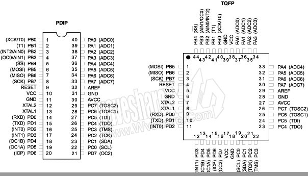
If you are a beginner and going through my datasheet for the first time, you won’t understand much and it is OK. Just have a look at my pinout diagram. You will see that most of the pins are named like this: PXY where X=A,B,C,D and Y=0 to 7. These are known as the I/O pins of the microcontroller. The other pins Vcc, GND, Reset, XTAL1, XTAL2, AVcc, AREF. You don’t need to care about the last four as of now. As for Vcc, that’s my mouth. If you want me to survive, you have to feed me. Just feed me a 5 Volt supply and a bit of current and I will be your genie! The GND pin SHOULD be connected to the circuit ground for best results.
I will now tell you about my various parts..err..ports.As for the PXY pins – I have 4 ‘ports’ – A,B,C and D (These will replace X). Each port has 8 pins – 0 to 7 (These will replace Y).
But what does I/O mean? I belong to the digital civilization and I follow TTL logic. In simple terms, I can’t differentiate between 0.2 Volts and 0.9 Volts because both are same for me – LOW. Similarly, I can’t differentiate between 3.6 Volts and 4.9 Volts because both are same for me – HIGH.
Practically,
0 to 1.4 Volts – LOW
3.4 to 5 Volts – HIGH
My inputs and outputs are always either HIGH or LOW. If any input or output is outside these ranges, well, don’t trust me. It is not my specialty!
Basic I/O configuration:
As I mentioned, 4 ports * 8 pins each = 32 I/O pins. But how do you tell me which pin you want to use? You do it using three ‘registers’. A ‘register’, in very simple terms, is nothing but a ‘group’ of 8 bits serving a similar purpose, generally. And this ‘group’ is given a name so that you can use it in your program to convey your desire to me.
The I/O registers commonly used are:
DDRX – DDR stands for Data Direction Register. This allows you to configure your pin as Input or Output. Now let me show you how to configure. Writing the following instruction (given inside single quotes):
‘DDRA = 0b11001001;’ – binary representation of port or ‘DDRA = 0xC9;’ – hexadecimal representation of Port. (Note: The pin order is 0b76543210)
Means that you want to set the pins 7,6,3 and 0 of Port A i.e Pins PA7, PA6, PA3 and PA0 as Output pins and the other pins of Port A as Input. By default all my 32 I/O pins are configured as Input i.e DDRX = 0b00000000.
PORTX – When you want to write either HIGH or LOW to a pin, you have to use my PORTX register. There are two cases:
1) Pin configured as Output
Let us continue with the above configuration i.e. DDRA = 0b11001001. If you now write the instruction,
Let us continue with the above configuration i.e. DDRA = 0b11001001. If you now write the instruction,
‘PORTA = 0b01000001;’
Focus only on Pins 7,6,3 and 0 which are configured as OUTPUT. A ‘0’ has been written to Pin 7 and 3 and a ‘1’ has been written to Pin 6 and 0. This means that if you connect your multimeter probes between Pin 7 and GND, the voltage will read ~0 Volts i.e. Pin 7 has been set to LOW. Same is the case with Pin 3. On the other hand, connection of probes between Pin 6 and GND results in a reading of ~5 Volts i.e. Pin 6 has been set to HIGH. Same is the case with Pin 0.
Basically, writing 1 to an OUTPUT pin sets it HIGH and writing 0 to an OUTPUT pin sets it LOW.
2) Pin configured as Input
Again, we will continue with the same pin configuration i.e. DDRA = 0b11001001. If you now write the instruction,
Again, we will continue with the same pin configuration i.e. DDRA = 0b11001001. If you now write the instruction,
‘PORTA = 0b00100010;’
Focus only on pins 5,4,2,1 which are configured as INPUT. A ‘0’ has been written to Pin 4 and 2 and a ‘1’ has been written to Pin 5 and 3. There is something called a pull-up resistor. The function of this is to simply pull the potential of the pin to HIGH. And writing a ‘1’ to the input-configured pin enables this resistor. Writing a ‘0’ to an input-configured pin does not do so and hence the pin is said to be ‘floating’. This is an undesirable condition as it can pick up stray potentials from the surroundings or the breadboard and can lead to erroneous results which are hard to debug if you don’t know about this concept (Trust me!). So the good habit is to always pull HIGH an input-configured pin by writing ‘1’ to it. Or alternatively, ground the input-configured pin, when not in use.
PINX – This is the register that stores the current status of each and every pin. So, if you want to read a particular pin, say 4th pin of Port B, all you have to do is:
1) Write the following instruction: ‘char c = PINB;’ – This will transfer the contents of the 8 bit register PINB into the 8 bit character instance ‘c’.
2) Since you want only the status of the 4th pin, perform a logical AND of ‘c’ with 0b00010000. What this will do is, it will clear all the bits except the 4th. If the 4th pin is HIGH, ANDing it with the above will give the result 0b00010000 (let us call it ‘g’) and 0b00000000 (let us call it ‘h’), if not.
3) Check the value of the ANDed result – if value is ‘g’, then the 4th pin was HIGH, if the value is ‘h’, the 4th pin was LOW.
NOTE: Some IDEs like Code Vision AVR also allow direct access of pins by commands like DDRB.1, PORTC.4, PINA.4 etc. which simplify my user’s life!
Coding:
Besides the knowledge of these registers for I/O, you also need to include some header files (if you are working in, say, AVR Studio). Code Vision AVR has a code wizard that performs all these formalities for you so that you can directly write your code!
Given below is a sample code for AVR Studio that shows you what all header files you should include and other things you need to initialize. Also the code includes the usage of a delay function (parameter in milliseconds) that introduces a delay in your program giving you time to observe your results. The result of burning this code into me will result in my pin PB0 going high and low alternatively at a 1 second interval.
#define F_CPU 1000000UL // CPU counts from o to 999999 in 1 second!
#include <avr/io.h>
#include <util/delay.h>
int main()
{
DDRB = 0b00000001;
while(1)
{
PORTB = 0b00000000;
_delay_ms(1000); // the parameter is 1000 ms = 1 second
PORTB = 0b00000001;
_delay_ms(1000);
}
}
Important links and references:
1) http://www.atmel.com/dyn/resources/prod_documents/doc2503.pdf - detailed datasheet with sample codes for each and every feature
2) http://iamsuhasm.wordpress.com/tutsproj/avr-gcc-tutorial/ - a very good I/O tutorial with graphics, but please note, there are mistakes in this tutorial
3) http://www.wvshare.com/img/pinout/ATmega32_l.jpg - pinout diagram
4) http://www.avrfreaks.net/ - THE BEST site to learn more about AVR microcontrollers and their features and tutorials and discussions and lots more!
Thank you for reading my post. I wish you luck and hope you are able to use me well for your robot!
I REALLY LIKED YOUR INTRODUCTION,,,, ie the ATMEGA32 is talking to the user....nice...Also its funny too....
ReplyDeleteHi Prashant,
ReplyDeleteI really liked your post..................I am in second year BTech electrical.
I am involved in one microcontroller based project.If you have any PDF regarding Atmega programming plz mail me. at iitd.indra@gmail.com
Hi Vinod. Thanks a lot :-)
ReplyDeleteHi Indra - I know this is coming a bit late. But, I think it is good advice. I would suggest you to take up small projects like blinking an LED or controlling a DC motor or get a simple PWM set up and then start thinking about the software part. It helps in effective learning. As far as support goes, www.avrfreaks.net is perhaps the best forum for beginners in microcontroller. I know it is AVR specific, but some posts like bit-manipulation, serial communication, PWM etc. are very general in their explanation. You can easily make the code if you sit with the datasheet of your mu-c. Hope this helps :)
hahaha....its very funny yet informative introduction...
ReplyDeleteKeep writing this kind of post... :)
hello
ReplyDeletethe introduction you provided is very much helpful.i am completely new to this topic but very much interested to learn, specially because of its application to robotics. but i am a student of mechanical engineering and that's why i am not getting much guidance.
Can you tell me how to learn it step by step? Also, if you provide me a list of books, it will be very much helpful.
Thanks.
Great work.
ReplyDeleteIt helped me a lot. Thanks :)
you are best, you saved my day.
ReplyDeleteI found one typo issue in Pin configured as Input :
‘1’ has been written to Pin 5 and 3.
I think it should read as ‘1’ has been written to Pin 5 and 1.
thanks
ReplyDelete